A class that models a GPIO outputs pins expander through the use of 8-bits Serial In Paralell Out (SIPO) shift registers. More...
#include <ShiftRegGPIOXpander_AVR.h>
Public Member Functions | |
| ShiftRegGPIOXpander () | |
| Class default constructor. | |
| ShiftRegGPIOXpander (uint8_t ds, uint8_t sh_cp, uint8_t st_cp, uint8_t srQty=1) | |
| Class constructor. | |
| ~ShiftRegGPIOXpander () | |
| Class destructor. | |
| bool | begin (uint8_t *initCntnt=nullptr) |
| GPIOXpander object setup and activation. | |
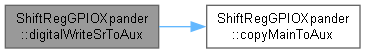
| bool | copyMainToAux (const bool &overWriteIfExists=true) |
| Copies the Buffer content to the Auxiliary Buffer. | |
| SRGXVPort | createSRGXVPort (const uint8_t &strtPin, const uint8_t &pinsQty) |
| Instantiate a SRGXVPort object. | |
| bool | digitalReadSgmntSr (const uint8_t &strtPin, const uint8_t &pinsQty, uint16_t &bffrSgmnt) |
| Returns a 16-bits value containing a zero-based segment of the Main Buffer. | |
| int | digitalRead (const uint8_t &srPin) |
| Returns the state of the requested pin of the ShiftRegGPIOXpander. | |
| uint8_t | digitalReadSr (const uint8_t &srPin) |
| Returns the state of the requested pin. | |
| bool | digitalToggleSr (const uint8_t &srPin) |
| Toggles the state of a specific pin. | |
| bool | digitalToggleSrAll () |
| Toggles the state of all the pins. | |
| bool | digitalToggleSrMask (uint8_t *toggleMask) |
| Toggles the state of the pins in the Main Buffer according to the provided mask. | |
| bool | digitalToggleSrToAux (const uint8_t &srPin) |
| Toggles the state of a specific pin in the Auxiliary Buffer. | |
| void | digitalWrite (const uint8_t &srPin, const uint8_t &value) |
| Set a specific pin to either HIGH (0x01) or LOW (0x00). | |
| bool | digitalWriteSr (const uint8_t &srPin, const uint8_t &value) |
| Set a specific pin to either HIGH (0x01) or LOW (0x00). | |
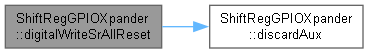
| bool | digitalWriteSrAllReset () |
| Sets all the pins to LOW (0x00/Reset). | |
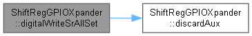
| bool | digitalWriteSrAllSet () |
| Sets all the pins to HIGH (0x01). | |
| bool | digitalWriteSrMaskReset (uint8_t *resetMask) |
| Modifies the Main buffer contents by resetting simultaneously certain pins. | |
| bool | digitalWriteSrMaskSet (uint8_t *setMask) |
| Modifies the Main buffer contents by setting simultaneously certain pins. | |
| bool | digitalWriteSrToAux (const uint8_t srPin, const uint8_t value) |
| Set a specific pin to either HIGH (0x01) or LOW (0x00) in the Auxiliary Buffer. | |
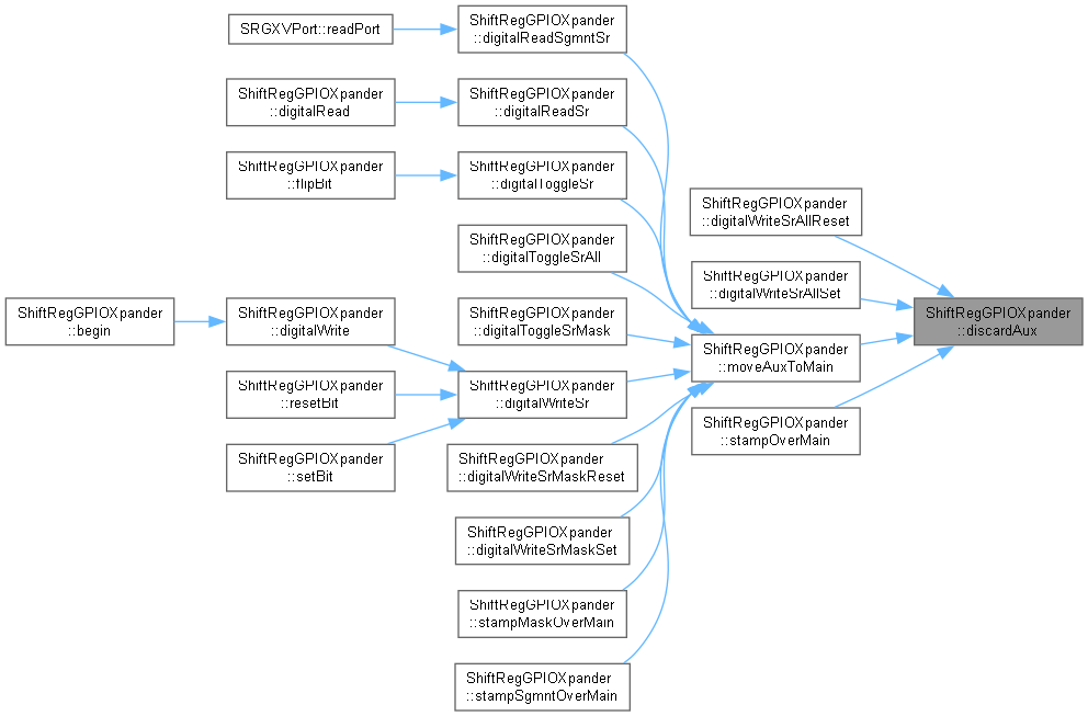
| bool | discardAux () |
| Deletes the Auxiliary Buffer. | |
| void | end () |
| Method provided for ending any relevant activation procedures made by the begin(uint8_t*) method. | |
| bool | flipBit (const uint8_t &srPin) |
| Toggles the state of a specific pin in the Main Buffer. | |
| uint8_t * | getMainBuffPtr () |
| Retrieves the pointer to the Main Buffer. | |
| uint8_t | getMaxSRGXPin () |
| Return the greatest valid pin number. | |
| uint8_t | getSrQty () |
| Return the quantity of shift registers composing the GPIOXtender object. | |
| bool | isValid (SRGXVPort &VPort) |
| Checks if the provided SRGXVPort object is valid. | |
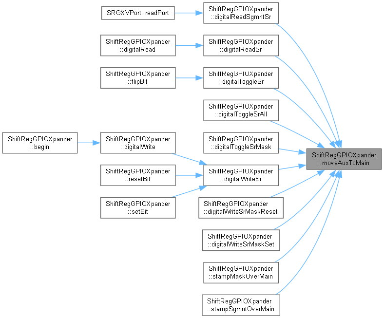
| bool | moveAuxToMain () |
| Moves the data in the Auxiliary to the Main. | |
| bool | resetBit (const uint8_t &srPin) |
| Sets a specific pin to LOW (0x00/Reset) in the Main Buffer. | |
| bool | setBit (const uint8_t &srPin) |
| Sets a specific pin to HIGH (0x01/Set) in the Main Buffer. | |
| bool | stampMaskOverMain (uint8_t *maskPtr, uint8_t *valsPtr) |
| Sets the value of several pins, scattered or contiguous, in the Main Buffer, according to the provided mask and values. | |
| bool | stampOverMain (uint8_t *newCntntPtr) |
| Sets all of the output pins of the shift register to new provided values at once. | |
| bool | stampSgmntOverMain (uint8_t *newSgmntPtr, const uint8_t &strtPin, const uint8_t &pinsQty) |
| Sets the value of a number of consecutive pins (the segment) in the Main Buffer. | |
Detailed Description
A class that models a GPIO outputs pins expander through the use of 8-bits Serial In Paralell Out (SIPO) shift registers.
The GPIO pins expansion modeled adds digital output pins managed by the use of an API similar to the built in Arduino platform tools. As the hardware is built using daisy-chained 74HCx595 shift registers, the connection pins to the first shift register are needed as parameters to build the object, as is the number of shift registers daisy-chain connected.
Being those three parameters hardware construction related, no mechanisms are provided to modify them after the object is created.
Constructor & Destructor Documentation
◆ ShiftRegGPIOXpander()
| ShiftRegGPIOXpander::ShiftRegGPIOXpander | ( | uint8_t | ds, |
| uint8_t | sh_cp, | ||
| uint8_t | st_cp, | ||
| uint8_t | srQty = 1 ) |
Class constructor.
Instantiates a ShiftRegGPIOXpander object, the parameters provide the pins used to communicate with the shift registers and the number of shift registers composing the expander. 8-bits will be added with every shift register connected in a daisy-chain arrangement.
- Parameters
-
ds MCU GPIO pin connected to the DS pin -a.k.a. serial data input (DIO)- pin of the 74HCx595 to send data serially to the expander sh_cp MCU GPIO pin connected to the SH_CP pin -a.k.a. shift register clock input- of the 74HCx595 to manage the communication's clock line to the expander st_cp MCU GPIO pin connected to the ST_CP pin -a.k.a. storage register clock input- to set (latch) the output pins from the internal buffer of the expander srQty Optional parameter. Quantity of shift registers set in daisy-chain configuration composing the expander.
- Note
- The object will create a dynamic array to buffer the information written to the shift registers, it will be referred to as Main Buffer, the Buffer or the Main.
The action of sending the Buffer contents to the shift registers array will be reffered to as Flushing. Every time the Buffer is flushed to the shift registers array the whole contents of that array will be sent.
A secondary dynamic array will be created for delayed operations purposes, that buffer will be referred to as Auxiliary Buffer or the Auxiliary. The Auxiliary will be created every time it's needed and destroyed after it's temporary use becomes unnecessary. The Auxiliary will be used to allow several bit changing operations without the need of flushing the whole buffer for each bit change. The usual propper use of the mechanism will make all the bits changes that occur simultaneously to the Auxiliary Buffer and then moving the Auxiliary Buffer to the Main Buffer and flushing the Buffer. See moveAuxToMain() method for more information.
-
There is no mechanism to flush the Auxiliary straight to the shift registers.
- Attention
- Every method that invokes a Main Buffer modification -see digitalWriteSr(const uint8_t, const uint8_t), digitalWriteSrAllReset(), digitalWriteSrAllSet(), digitalWriteSrMaskReset(uint8_t*), digitalWriteSrMaskSet(uint8_t*) - and/or flushing -see bool _sendAllSRCntnt() - will force first the Auxiliary to be moved over the Main Buffer, destroy the Auxiliary, perform the intended operation over the Main Buffer and then finally flush the resulting Main Buffer contents to the shift registers. This procedure is enforced to guarantee buffer contents consistency and avoid any loss of modifications done to the Auxiliary. The digitalReadSr(const uint8_t) method will also invoke a moveAuxToMain() before returning the requested pin state. See digitalReadSr(const uint8_t) for more information.
◆ ~ShiftRegGPIOXpander()
| ShiftRegGPIOXpander::~ShiftRegGPIOXpander | ( | ) |
Class destructor.
Takes care of resources releasing
Member Function Documentation
◆ begin()
| bool ShiftRegGPIOXpander::begin | ( | uint8_t * | initCntnt = nullptr | ) |
GPIOXpander object setup and activation.
This method sets the controller pins configuration, and optionally sets the initial pin values for the GPIOXpander pins.
- Parameters
-
initCntnt Optional parameter. Initial value to be loaded into the Main Buffer, and thus will be the inital state of the Shift Register output pins. The value is provided in the form of a uint8_t*, and the constructor expects the data to be set in the memory area from the pointed address to the pointed address + (srQty - 1) consecutive bytes. If the parameter is not provided, or set to nullptr the inital value to be loaded into the Main Buffer will be 0x00 to all the shift registers positions, making all pins' output 0/LOW/RESET.
- Returns
- The success of the operation.
- Return values
-
true The operation was successful, the GPIOXpander object is ready to be used. false The operation failed, either because the pins could not be set, or the mutexes could not be created.

◆ copyMainToAux()
| bool ShiftRegGPIOXpander::copyMainToAux | ( | const bool & | overWriteIfExists = true | ) |
Copies the Buffer content to the Auxiliary Buffer.
- If there's no existent Auxiliary the method creates it and copies the content of the Main.
- If there's an Auxiliary, the method will proceed according to the value passed in the parameter overWriteIfExists:
- If the parameter passed is true the Auxiliary contents will be overwritten with the Main contents.
- If the parameter passed is false the Auxiliary will not be modified and the method will return a false to flag the failure of the operation.
- Parameters
-
overWriteIfExists Indicates the authorization to overwrite the Auxiliary with the contents of the Main Buffer if the Auxiliary exists at the moment of the invocation.
- Returns
- The success of the overwriting operation.
- Return values
-
true The Auxiliary was non-existent, or existed and the parameter allowing overwriting was true.
false The Auxiliary was existent and the parameter allowing overwriting was false, generating a failure in the operation.
◆ createSRGXVPort()
| SRGXVPort ShiftRegGPIOXpander::createSRGXVPort | ( | const uint8_t & | strtPin, |
| const uint8_t & | pinsQty ) |
Instantiate a SRGXVPort object.
The method will create a SRGXVPort object, a virtual port that will allow the user to manipulate a set of pins as a single entity, with it's pins numbered from 0 to pinsQty - 1, where pinsQty is the number of pins that compose the virtual port.
- Parameters
-
strtPin ShiftRegGPIOXpander pin number from which the virtual port will start. The valid range is 0 <= strtPin <= getMaxSRGXPin(). pinsQty Number of pins that will compose the virtual port. The valid range is 1 <= pinsQty <= 16
- Returns
- SRGXVPort The SRGXVPort object created, or an empty SRGXVPort object if the parameters provided were not valid.
- Attention
- Note that as described, the minimum amount of pins that can be set in a virtual port is 1, and the maximum amount of pins that can be set in a virtual port is equal to 16.
◆ digitalRead()
| int ShiftRegGPIOXpander::digitalRead | ( | const uint8_t & | srPin | ) |
Returns the state of the requested pin of the ShiftRegGPIOXpander.
- Parameters
-
srPin Pin whose current value is required.
- Returns
- The state value of the requested pin, either HIGH (0x01/Set) or LOW (0x00/Reset)
- Return values
-
0x00 The pin state was LOW 0x01 The pin state was HIGH -1 ERROR, the pin number was beyond implemented number of pins of the ShiftRegGPIOXpander object.
- Note
- The method's name, digitalRead(), is identical to the Arduino's digitalRead() method to facilitate the addition of this library with the least amount of changes to existing code, just adding the ShiftRegGPIOXpander object instantitated before existing digitalRead() calls and providing the correct pin number as parameter.
- Attention
- The value is retrieved from the object's Buffer, not the real chip. If a change to the Auxiliary was made by using the digitalWriteAux(const uint8_t, uint8_t) method (deferred update digital output pin value setting), without updating the Main Buffer an inconsistency might appear if the srPin to be read value is different in the Main from the Auxiliary. For ensuring data consistency the method checks for the Auxiliary existence, if the Auxiliary exists a moveAuxToMain(true) will be performed before returning the pin state.
- Warning
- If a moveAuxToMain(true) had to be executed, the Auxiliary will be destroyed. This will have no major consequences as every new need of the Auxiliary will automatically create a new instance of that buffer, but keep this concept in mind.

◆ digitalReadSgmntSr()
| bool ShiftRegGPIOXpander::digitalReadSgmntSr | ( | const uint8_t & | strtPin, |
| const uint8_t & | pinsQty, | ||
| uint16_t & | bffrSgmnt ) |
Returns a 16-bits value containing a zero-based segment of the Main Buffer.
The method will return a 16-bits value containing the bits from the Main Buffer delimited by the parameters provided, formatted as a zero-based segment (or right aligned value), meaning that the first bit of the segment will hold the value of the strtPin parameter, and subsequent bits will hold the values of the following pins, up to the pinsQty parameter.
- Note
- The retuning value will be a 16-bits value, even if the segment requested is smaller than 16 bits. The bits in the returned value will be right aligned, and zero padded, meaning that if the segment requested is smaller than 16 bits, the leftmost bits of the returned value will be set to 0x00.
- Parameters
-
strtPin The first pin number from which the segment will be taken. The valid range is 0 <= strtPin <= getMaxSRGXPin(). pinsQty The number of pins that will compose the segment. The valid range is 1 <= pinsQty <= (_maxSRGXPin - strtPin + 1). buffSgmnt A reference to a uint16_t variable where the segment will be stored. The variable must be initialized before calling the method, and it will be set to 0 before setting the segment bits.
- Returns
- A boolean value indicating the success of the operation.
- Return values
-
true The segment was successfully retrieved and stored in the buffSgmnt variable. false The parameters provided were not valid, or the operation failed for any other reason.
- Attention
- The method is tightly related to the SRGXVPort class, which uses it to retrieve the segment of the Main Buffer that corresponds to the virtual port being manipulated. The SRGXVPort class will ensure that the parameters provided are valid before calling this method.


◆ digitalReadSr()
| uint8_t ShiftRegGPIOXpander::digitalReadSr | ( | const uint8_t & | srPin | ) |
Returns the state of the requested pin.
- Parameters
-
srPin Pin whose current value is required.
- Returns
- The state value of the requested pin, either HIGH (0x01/Set) or LOW (0x00/Reset)
- Return values
-
0x00 The pin state was LOW 0x01 The pin state was HIGH 0xFF ERROR, the pin number was beyond implemented limit
- Attention
- The value is retrieved from the object's Buffer, not the real chip. If a change to the Auxiliary was made by using the digitalWriteAux(const uint8_t, uint8_t) method (deferred update digital output pin value setting), without updating the Main Buffer an inconsistency might appear if the srPin to be read value is different in the Main from the Auxiliary. For ensuring data consistency the method checks for the Auxiliary existence, if the Auxiliary exists a moveAuxToMain(true) will be performed before returning the pin state.
- Warning
- If a moveAuxToMain(true) had to be executed, the Auxiliary will be destroyed. This will have no major consequences as every new need of the Auxiliary will automatically create a new instance of that buffer, but keep this concept in mind.


◆ digitalToggleSr()
| bool ShiftRegGPIOXpander::digitalToggleSr | ( | const uint8_t & | srPin | ) |
Toggles the state of a specific pin.
The method will set the pin to LOW (0x00) if it was HIGH (0x01) and vice versa. The method will flush the buffer, so the change will be reflected on the GPIO pin.
- Parameters
-
srPin A positive value indicating which pin to toggle. The valid range is 0 <= srPin <= getMaxSRGXPin()
- Attention
- As the value is written to the object's Buffer, the existence of the Auxiliary (by a deferred update digital output pin value setting), an inconsistency might appear if the srPin to be written value is different in the Main from the Auxiliary. For ensuring data consistency the method checks for the Auxiliary existence, if the Auxiliary exists a moveAuxToMain(false) will be performed before seting the new pin state.
- Warning
- If a moveAuxToMain(false) had to be executed, the Auxiliary will be destroyed. This will have no major consequences as every new need of the Auxiliary will automatically create a new instance of that buffer, but keep this concept in mind.
- Returns
- A boolean value indicating the success of the operation.
- Return values
-
true The operation was successful, the pin was toggled in the Main Buffer and the change was flushed to the GPIO pin. false The operation failed, because the pin number was beyond the implemented limit.


◆ digitalToggleSrAll()
| bool ShiftRegGPIOXpander::digitalToggleSrAll | ( | ) |
Toggles the state of all the pins.
The method will set all the pins to LOW (0x00) if they were HIGH (0x01) and vice versa. The method will flush the buffer, so the change will be reflected on all the GPIO pins.
- Attention
- As the values are written to the object's Buffer, the existence of the Auxiliary (by a deferred update digital output pin value setting), an inconsistency might appear if the pins to be written values are different in the Main from the Auxiliary. For ensuring data consistency the method checks for the Auxiliary existence, if the Auxiliary exists a discardAux() will be performed before seting the new pin states.
- Returns
- A boolean value indicating the success of the operation.
- Return values
-
true Always, the operation was successful, all the pins were toggled in the Main Buffer and the change was flushed to the GPIO pins. The boolean return type is kept for versions compatibility.

◆ digitalToggleSrMask()
| bool ShiftRegGPIOXpander::digitalToggleSrMask | ( | uint8_t * | toggleMask | ) |
Toggles the state of the pins in the Main Buffer according to the provided mask.
The pins to be toggled are provided as a pointer to a mask parameter. Every bit position set (HIGH, 0x01) on the mask will be modified in the Main Buffer, reset pins (LOW, 0x00) positions of the mask will remain unmodified in the Main Buffer. The modification performed will be toggling the bit position.
- Parameters
-
toggleMask Pointer to the array containing the mask to modify the Main.
- Note
- The method provides a mechanism for toggling various Main buffer bit positions in a single operation.
- Attention
- Any modifications made in the Auxiliary will be moved to the Main and it will be deleted before applying the mask.
- Returns
- A boolean value indicating the success of the operation.
- Return values
-
true The operation was successful, the pins were toggled in the Main Buffer and the change was flushed to the GPIO pins. false The operation failed, because the mask was null.

◆ digitalToggleSrToAux()
| bool ShiftRegGPIOXpander::digitalToggleSrToAux | ( | const uint8_t & | srPin | ) |
Toggles the state of a specific pin in the Auxiliary Buffer.
- Parameters
-
srPin A positive value indicating which pin to toggle. The valid range is 0 <= srPin <= getMaxSRGXPin().
- Attention
- The pin modified in the Auxiliary will not be reflected on the pins of the GPIOXpander until the Auxiliary Buffer is copied into the Main Buffer and the latter one is flushed. This method's main purpose is to modify more than one pin that must be modified at once and then proceed with the bool moveAuxToMain(bool).
- Note
- An alternative procedure analog to the use of .print() and .println() methods is to invoke the several digitalToggleSrToAux() methods needed but the last, and then invoking a digitalToggleSr(const uint8_t) for the last pin writing. This last method will take care of moving the Auxiliary to the Main, set that last pin value and flush the Main Buffer.
- Returns
- A boolean value indicating the success of the operation.
- Return values
-
true The operation was successful, the pin was toggled in the Auxiliary Buffer. false The operation failed because the pin number was beyond the implemented limit.

◆ digitalWrite()
| void ShiftRegGPIOXpander::digitalWrite | ( | const uint8_t & | srPin, |
| const uint8_t & | value ) |
Set a specific pin to either HIGH (0x01) or LOW (0x00).
- Parameters
-
srPin a positive value indicating which pin to set. The valid range is 0 <= srPin <= getMaxSRGXPin()
value Value to set the indicated Pin.
- Note
- The method's name, digitalWrite(), is identical to the Arduino's digitalWrite() method to facilitate the addition of this library with the least amount of changes to existing code, just adding the ShiftRegGPIOXpander object instantitated before existing digitalRead() calls and providing the correct pin number as parameter.


◆ digitalWriteSr()
| bool ShiftRegGPIOXpander::digitalWriteSr | ( | const uint8_t & | srPin, |
| const uint8_t & | value ) |
Set a specific pin to either HIGH (0x01) or LOW (0x00).
- Parameters
-
srPin a positive value indicating which pin to set. The valid range is 0 <= srPin <= getMaxSRGXPin()
value Value to set the indicated Pin.
- Attention
- As the value is written to the object's Buffer, the existence of the Auxiliary (by a deferred update digital output pin value setting) might generate an inconsistency if the srPin to be written value is different in the Main from the Auxiliary. For ensuring data consistency the method checks for the Auxiliary existence, if the Auxiliary exists a moveAuxToMain(false) will be performed before seting the new pin state.
- Warning
- If a moveAuxToMain(false) had to be executed, the Auxiliary will be destroyed. This will have no major consequences as every new need of the Auxiliary will automatically create a new instance of that buffer, but keep this concept in mind.
- Returns
- A boolean value indicating the success of the operation.
- Return values
-
true The operation was successful, the pin was set in the Main Buffer and the change was flushed to the GPIO pin. false The operation failed because the pin number was beyond the implemented limit.

◆ digitalWriteSrAllReset()
| bool ShiftRegGPIOXpander::digitalWriteSrAllReset | ( | ) |
Sets all the pins to LOW (0x00/Reset).
- Attention
- As the new values are written to the object's Buffer, the existence of the Auxiliary might produce an inconsistency to appear. For ensuring data consistency the method checks for the Auxiliary existence, if the Auxiliary exists a discardAux() will be performed before setting the new values to the Main.
- Warning
- If discardAux() has to be executed, the Auxiliary will be destroyed. This will have no major consequences as every new need of the Auxiliary will automatically create a new instance of that buffer, but keep this concept in mind.
- Returns
- A boolean value indicating the success of the operation.
- Return values
-
true Always, the operation was successful, all the pins were set to LOW in the Main Buffer and the change was flushed to the GPIO pins. The boolean return type is kept for compatibility with other library versions.
◆ digitalWriteSrAllSet()
| bool ShiftRegGPIOXpander::digitalWriteSrAllSet | ( | ) |
Sets all the pins to HIGH (0x01).
- Attention
- As the new values are written to the object's Buffer, the existence of the Auxiliary might produce an inconsistency to appear. For ensuring data consistency the method checks for the Auxiliary existence, if the Auxiliary exists a discardAux() will be performed before setting the new values to the Main.
- Warning
- If discardAux() had to be executed, the Auxiliary will be destroyed. This will have no major consequences as every new need of the Auxiliary will automatically create a new instance of that buffer, but keep this concept in mind.
- Returns
- A boolean value indicating the success of the operation.
- Return values
-
true Always, the operation was successful, all the pins were set to HIGH in the Main Buffer and the change was flushed to the GPIO pins. The boolean return type is for compatibility with other library versions.
◆ digitalWriteSrMaskReset()
| bool ShiftRegGPIOXpander::digitalWriteSrMaskReset | ( | uint8_t * | resetMask | ) |
Modifies the Main buffer contents by resetting simultaneously certain pins.
The pins to be reset are provided as a pointer to a mask parameter. Every bit position set (HIGH, 0x01) on the mask will be modified in the Main Buffer, reset pins (LOW, 0x00) positions of the mask will remain unmodified in the Main Buffer. The modification performed will be setting the bit position to LOW (0x00).
- Parameters
-
resetMask Pointer to the array containing the mask to modify the Main.
- Note
- The method provides a mechanism for clearing (reseting/lowering) various Main buffer bit positions in a single operation.
- Attention
- Any modifications made in the Auxiliary will be moved to the Main and will be deleted before applying the mask.
- The Main Buffer will be flushed after the mask modifications are applied.
- Returns
- A boolean value indicating the success of the operation.
- Return values
-
true The operation was successful, the pins were reset in the Main Buffer and the change was flushed to the GPIO pins. false The operation failed because the mask pointer was null.

◆ digitalWriteSrMaskSet()
| bool ShiftRegGPIOXpander::digitalWriteSrMaskSet | ( | uint8_t * | setMask | ) |
Modifies the Main buffer contents by setting simultaneously certain pins.
The pins to be set are provided as a parameter pointer to a mask. Every bit position set (HIGH, 0x01) on the mask will be modified in the Main Buffer, reset pins (LOW, 0x00) positions of the mask will remain unmodified in the Main Buffer. The modification performed will be setting the bit position to HIGH (0x01).
- Parameters
-
setMask Pointer to the array containing the mask to modify the Main.
- Note
- The method provides a mechanism for seting (rising) various Main buffer bit positions in a single operation.
- Attention
- Any modifications made in the Auxiliary will be moved to the Main and will be deleted before applying the mask.
- The Main Buffer will be flushed after the mask modifications are applied.
- Returns
- A boolean value indicating the success of the operation.
- Return values
-
true The operation was successful, the pins were set in the Main Buffer and the change was flushed to the GPIO pins. false The operation failed because the mask pointer was null.

◆ digitalWriteSrToAux()
| bool ShiftRegGPIOXpander::digitalWriteSrToAux | ( | const uint8_t | srPin, |
| const uint8_t | value ) |
Set a specific pin to either HIGH (0x01) or LOW (0x00) in the Auxiliary Buffer.
- Parameters
-
srPin a positive value indicating which pin to set. The valid range is 0 <= srPin <= getMaxSRGXPin() value Value to set for the indicated Pin.
- Attention
- The pin modified in the Auxiliary will not be reflected on the pins of the GPIOXpander until the Auxiliary Buffer is copied into the Main Buffer and the latter one is flushed. This method main purpose is to modify several pins at once and then proceed with the bool moveAuxToMain(bool).
- Note
- An alternative procedure analog to the use of .print() and .println() methods is to invoke the several digitalWriteSrToAux() methods needed but the last, and then invoking a digitalWrite(const uint8_t, const uint8_t) for the last pin writing. This last method will take care of moving the Auxiliary to the Main, set that last pin value and flush the Main Buffer.
- Returns
- A boolean value indicating the success of the operation.
- Return values
-
true The operation was successful, the pin was set in the Auxiliary Buffer. false The operation failed because the pin number was beyond the implemented limit.
◆ discardAux()
| bool ShiftRegGPIOXpander::discardAux | ( | ) |
Deletes the Auxiliary Buffer.
Discards the contents of the Auxiliary Buffer, frees the memory allocated to it and nullifies the corresponding memory pointer. If the Auxiliary Buffer was not created, the method will do nothing. If the Auxiliary is not transferred to the Main Buffer before invoking this method, the modified contents of the Auxiliary will be lost.
- Returns
- A boolean value indicating the success of the operation.
- Return values
-
true Always, the Auxiliary Buffer was successfully discarded, and the memory allocated to it was freed. The boolean type return value is kept for library versions compatibility
◆ end()
| void ShiftRegGPIOXpander::end | ( | ) |
Method provided for ending any relevant activation procedures made by the begin(uint8_t*) method.
The method will be invoked as part of the class destructor.
◆ flipBit()
| bool ShiftRegGPIOXpander::flipBit | ( | const uint8_t & | srPin | ) |
Toggles the state of a specific pin in the Main Buffer.
- Parameters
-
srPin Pin whose state is to be toggled. The valid range is 0 <= srPin <= getMaxSRGXPin()
- Return values
-
true The pin was in the valid range and was toggled in the Main Buffer. false The pin was not in the valid range, and no action was taken.
- Note
- flipBit(n) is a synonym for digitalToggleSr(n), and is provided for shortening and using more meaningful name in the code.

◆ getMainBuffPtr()
| uint8_t * ShiftRegGPIOXpander::getMainBuffPtr | ( | ) |
Retrieves the pointer to the Main Buffer.
- Returns
- Pointer to the array of uint8_t holding the buffered shift registers values.
- Note
- The returned array's length is equal to the number of shift registers set in daisy-chain, see uint8_t getSrQty() for information.
◆ getMaxSRGXPin()
| uint8_t ShiftRegGPIOXpander::getMaxSRGXPin | ( | ) |
Return the greatest valid pin number.
The greatest valid pin number is directly related to the quantity of shift registers connected, and is equal to the number of shift registers multiplied by 8 minus 1, (getSrQty() * 8) - 1.
- Returns
- uint8_t maxPin number value.
- Note
- The value will be used as a limit for the pin numbers to be used in the digitalWriteSr(const uint8_t, const uint8_t) and digitalReadSr(const uint8_t) methods.

◆ getSrQty()
| uint8_t ShiftRegGPIOXpander::getSrQty | ( | ) |
Return the quantity of shift registers composing the GPIOXtender object.
The value is passed as a parameter in the class constructor.
- Returns
- uint8_t The number of shift registers composing the physical port extender modeled by the class.
◆ isValid()
| bool ShiftRegGPIOXpander::isValid | ( | SRGXVPort & | VPort | ) |
Checks if the provided SRGXVPort object is valid.
The method is useful to verify after a createVXVPort(uint8_t&, uint8_t&) invocation that the SRGXVPort object created is valid, i.e. that it was created with a valid ShiftRegGPIOXpander object pointer and that the parameters provided to create the SRGXVPort object were valid.
- Parameters
-
VPort SRGXVPort object to be checked for validity.
- Returns
- true The created SRGXVPort object is valid and usable.
- false The created SRGXVPort object is not valid, and should not be used.
- Note
- If the method returns false, the SRGXVPort object should not be used. Consider destructing it and creating a new one with valid parameters.
◆ moveAuxToMain()
| bool ShiftRegGPIOXpander::moveAuxToMain | ( | ) |
Moves the data in the Auxiliary to the Main.
Moving the contents from the Auxiliary to the Main implies several steps:
- Check the existence of the Auxiliary
- Copy the contents from the Auxiliary to the Main (see stampOverMain(uint8_t*))
- Delete the Auxiliary (see discardAux())
- Returns
- The success of moving the data from the Auxiliary to the Main.
- Return values
-
true There was an Auxiliary and it's value could be moved.
false There was no Auxiliary present, no data have been moved.
◆ resetBit()
| bool ShiftRegGPIOXpander::resetBit | ( | const uint8_t & | srPin | ) |
Sets a specific pin to LOW (0x00/Reset) in the Main Buffer.
- Parameters
-
srPin Pin whose state is to be reset. The valid range is 0 <= srPin <= getMaxSRGXPin()
- Return values
-
true The pin was in the valid range and was reset to LOW (0x00/Reset) in the Main Buffer. false The pin was not in the valid range, and no action was taken.
- Note
- resetBit(n) is a synonym for digitalWriteSr(n, LOW), and is provided for shortening and using more meaningful name in the code.

◆ setBit()
| bool ShiftRegGPIOXpander::setBit | ( | const uint8_t & | srPin | ) |
Sets a specific pin to HIGH (0x01/Set) in the Main Buffer.
- Parameters
-
srPin Pin whose state is to be set. The valid range is 0 <= srPin <= getMaxSRGXPin()
- Return values
-
true The pin was in the valid range and was set to HIGH (0x01/Set) in the Main Buffer. false The pin was not in the valid range, and no action was taken.
- Note
- setBit(n) is a synonym for digitalWriteSr(n, HIGH), and is provided for shortening and using more meaningful name in the code.

◆ stampMaskOverMain()
| bool ShiftRegGPIOXpander::stampMaskOverMain | ( | uint8_t * | maskPtr, |
| uint8_t * | valsPtr ) |
Sets the value of several pins, scattered or contiguous, in the Main Buffer, according to the provided mask and values.
- Parameters
-
maskPtr Pointer to the memory area containing the mask to be applied to the Main Buffer. The mask is a bit array where each bit position set (HIGH, 0x01) indicates that the corresponding pin in the Main Buffer will be modified with the value provided in the newValsPtr parameter. valsPtr Pointer to the memory area containing the values to be set in the Main Buffer. The values are provided as a bit array, where each bit position corresponds to the pin in the Main Buffer that will be modified according to the mask provided in the newMaskPtr parameter: for the array positions set in the mask, the value of the bit in the newValsPtr will be set in the corresponding pin in the Main Buffer, for the array positions not set in the mask, the value in the Main Buffer will remain unchanged.
- Return values
-
true Main Buffer was modified with the new values and flushed to the shift registers. false Main Buffer was not modified, either because the parameters provided were not valid.

◆ stampOverMain()
| bool ShiftRegGPIOXpander::stampOverMain | ( | uint8_t * | newCntntPtr | ) |
Sets all of the output pins of the shift register to new provided values at once.
The method gives a tool to change all the shift registers pins in one operation instead of pin by pin. The method uses the provided pointer as a data source to overwrite the Main Buffer with the new contents.
- Parameters
-
newCntntPtr A uint8_t* pointing the memory area containing the new values to be set to the buffer.
- Returns
- Success in overwriting the Buffer.
- Return values
-
true The Buffer was overwritten and the new contents flushed.
false The parameter passed was a nullptr/NULL and no overwriting was possible.
- Attention
- If there was an ongoing set of deferred pin modifications through the use of writes to the Auxiliary they will be all lost, as the first data consistency prevention of the method is to discard the Auxiliary.
- Warning
- As soon as the Main is overwritten with the new values, the Buffer will be flushed.
◆ stampSgmntOverMain()
| bool ShiftRegGPIOXpander::stampSgmntOverMain | ( | uint8_t * | newSgmntPtr, |
| const uint8_t & | strtPin, | ||
| const uint8_t & | pinsQty ) |
Sets the value of a number of consecutive pins (the segment) in the Main Buffer.
Each pin value is set or reset according to the value provided in the data array pointed by the newSgmntPtr parameter as source.
- Parameters
-
newSgmntPtr Pointer to the memory area containing the new values to be set to the segment of pins in the Main Buffer. The value to be set in each pin is provided as a bit in the data pointed by the newSgmntPtr parameter, where the first bit in the data pointed by newSgmntPtr will be set to the first pin in the segment, and so on. For that logic to work the data must be right aligned (LSb of the segment placed in position 0) in the data pointed by newSgmntPtr.
strtPin First pin number in the Main buffer to be overwritten. The valid range is 0 <= strtPin <= getMaxSRGXPin(). pinsQty The number of pins to be set in the segment. The valid range is 1 <= pinsQty <= (getMaxSRGXPin() - strtPin + 1).
- Returns
- A boolean indicating the success of the operation.
- Return values
-
true The segment was set in the Main Buffer and the Buffer was flushed.
false The segment could not be set in the Main Buffer because the parameters provided were not valid.
- Note
- The intended behavior of the method is to present the resulting Main in a single operation, so the method will make all the segment modifications to the Main Buffer before flushing it. If the Auxiliary Buffer contains any pending modifications, they will be moved to the Main Buffer before the segment stamping execution.
- Warning
- The method expects newSgmntPtr to point to a valid memory area containing the data to be set in the segment. If the pointer is nullptr/NULL, the method will return false and no operation will be performed.
- Attention
- Although the method, as all similar methods in the class, expects the data pointed by newSgmntPtr to be the same length as the Main Buffer, it will only use the first pinsQty bits of the data pointed by newSgmntPtr, so the data pointed by newSgmntPtr must be at least pinsQty bits long, that means that the data pointed by newSgmntPtr must be at least ceil(pinsQty / 8) bytes long.
